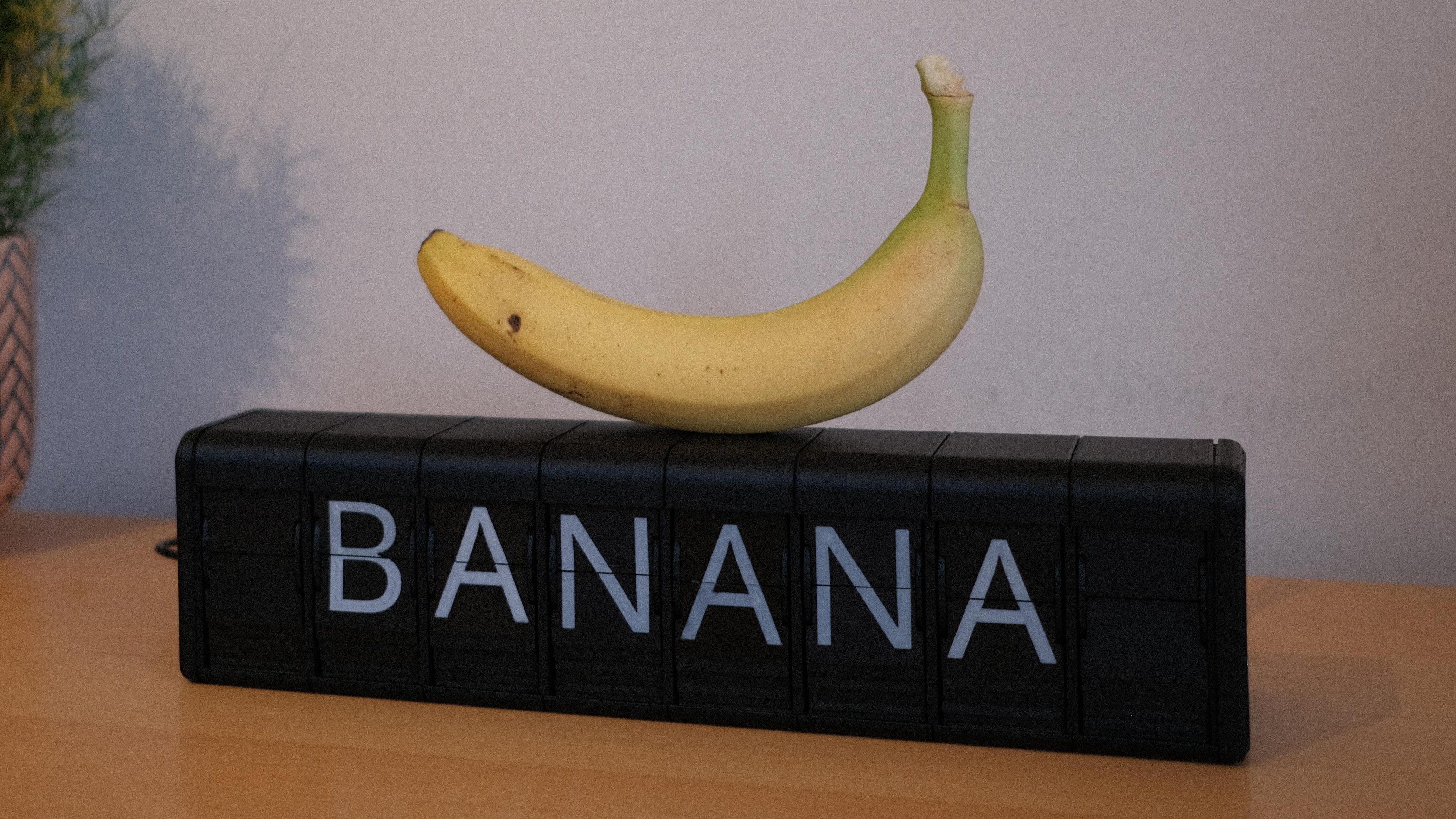
There are two kinds of people in this world: people who love sleek, silent OLED screens… and people who want their desk to sound like a tiny, well-mannered train station. If you’re reading this, you’re probably in the second camp (welcome; we have snacks, and they click).
A 3D printed split-flap display is equal parts nostalgia machine and mechanical flex. It’s also a surprisingly practical build: each module is just a rotating drum of flaps, a motor, a way to “home” the position so it doesn’t lie to you, and a controller that tells it what to say. Print the parts, assemble the mechanism, wire the electronics, load firmware, calibrate, then enjoy the most satisfying “clack-clack-clack” your workspace has ever produced.
Why Split-Flap Displays Still Hit Different
Split-flap boards were designed for legibility at a distance, reliability, and easy maintenance. Their modern superpower is emotional: the motion draws your eye, and the sound makes the message feel “real.” A split-flap clock doesn’t just show the timeit performs it, like a tiny stagehand swapping props at the exact right moment.
And in a world of infinite pixels, building a mechanical display is refreshingly finite. You can’t “just add another font.” You pick a character set, print it, and commit. It’s the maker equivalent of writing with a fountain pen: slower, fussier, and weirdly delightful.
How a Split-Flap Module Works (Without the Mythology)
The basic mechanism
A single module displays one character. Inside, a motor turns a drum that carries a loop of flaps. Each flap is a half-card that flips over a pivot as the drum rotates, landing in a “window” where you can read it. The drum keeps turning until the requested character reaches the window, then stops.
Homing: how your display learns where “A” actually is
The tricky part isn’t spinning flapsit’s knowing which flap is currently showing after power loss, missed steps, or a curious cat. DIY split-flap displays typically solve this with a sensor-based “home” reference:
- Hall-effect sensor + magnet: A magnet on (or near) a specific flap triggers the sensor once per rotation.
- Endstop/limit switch: A mechanical switch triggers when a tab or cam passes by.
- Mechanical latch homing: Some designs use clever geometry so the mechanism naturally resets without extra sensors.
Once you can reliably find “home,” the rest is math: the firmware counts steps to reach the desired character and stores a small offset so each module lines up perfectly in its window.
Choose Your Build Style: Tiny Desk Toy or Modular Message Wall?
Before you print anything, pick an architecture. This determines cost, wiring complexity, and how much future-you will mutter under your breath while debugging.
Option A: One module, one microcontroller
Simple and satisfying. Great for a single-character status indicator (“OK”, “NO”, “WHY”). Each unit has its own MCU, motor driver, and sensor. Easy to understand, slightly annoying to scale.
Option B: Modular chain controlled by one “brain”
Best for clocks, tickers, and message boards. A master controller (often Wi-Fi capable) sends commands to multiple modules. Many builders use I2C or a similar bus to keep wiring manageable.
Option C: “Desk-ready” enclosed modules
If you want something that looks less like a science fair and more like a product, choose a design with a tidy enclosure and concealed wiring. You’ll print more pieces, but you’ll also leave it on your desk instead of “temporarily storing it” in a box for nine months.
Motors and Drivers: The Two Most Common Paths
The budget favorite: 28BYJ-48 + ULN2003
The 28BYJ-48 stepper motor is popular because it’s cheap, geared, and easy to drive with a ULN2003 board. It’s commonly used in compact DIY split-flap modules. The tradeoff: it’s not the strongest motor on Earth, so your mechanism must be low-friction and well-aligned.
For a typical split-flap module, the geared reduction helps maintain torque at low speeds, and the step count is high enough to position flaps precisely. The big “pro move” here is power: give the motor its own stable 5V supply instead of stealing current from a microcontroller board that’s already busy being a microcontroller board.
The upgrade path: NEMA 17 (or similar) + A4988-style driver
If you want more torque, faster indexing, and fewer “it skipped a step and now it’s gaslighting me” moments, a bipolar stepper with a driver like the A4988 is a common choice. These drivers typically use STEP/DIR signals, so your code can be clean and timing-friendly.
This setup can be extremely reliableif you set current limits properly and manage heat. In other words: it’s powerful, but it expects you to act like an adult.
The Brains: Arduino, ESP32, ESP8266, and Friends
The controller choice depends on whether you want networking. If you want a simple clock, an Arduino-class MCU is plenty. If you want a web interface, MQTT, OTA updates, or pulling time from the internet, ESP32/ESP8266 boards are common.
A popular scalable approach is a “master + modules” design where the master hosts a web UI and sends characters to individual modules over a bus. This keeps the user experience modern while the display remains gloriously mechanical.
3D Printing the Hardware: Where Success Is Won (or Lost)
Material selection: strength vs. smooth motion
For prototypes, PLA is fast and dimensionally stable. For parts that rub, flex, or get warm (like motor mounts near drivers), PETG can be a good upgrade. Whatever you choose, prioritize repeatability and fit: split-flap mechanisms hate vague tolerances.
Design for clearance, not optimism
Moving parts need clearancemore than you think, and more than your ego wants to admit. A tiny bit of elephant’s foot or a slightly over-extruded hole can turn a smooth drum into a plastic paperweight.
- Print test coupons for axle holes and bearing seats before committing to a full set of parts.
- Oversize holes and finish with a reamer/drill bit for clean, round fits.
- Plan for service: you will open this thing again. Make it easy on yourself.
Flaps: the tiny divas of the whole project
Flaps must flip cleanly, align in the window, and survive thousands of cycles. Common strategies:
- Two-color printing: swap filament at a layer height to create high-contrast characters.
- Stickers/decals: fast iteration when you’re still changing the character set.
- Balanced geometry: avoid thick/heavy flaps that slam and bounce.
If you want the classic “airport board” vibe, choose a character set that includes a blank flap plus letters, numbers, and a few symbols. Many DIY modules land around a few dozen charactersenough to be useful, not so many that printing becomes your full-time job.
Bearings, axles, and the art of not sounding like a blender
Your display will make noise (that’s part of the charm), but it shouldn’t sound distressed. Bearings can help keep the drum stable. If you’re using printed pins as pivots, consider wear: a smoother pin material or a small metal axle can dramatically improve longevity.
Electronics: A Simple, Reliable Wiring Plan
Keep electronics boring. Boring electronics are the best electronics.
Typical block diagram (per module)
- Microcontroller (Arduino/ESP32/etc.)
- Motor driver (ULN2003 for 28BYJ-48, or A4988-style for bipolar steppers)
- Home sensor (hall sensor + magnet, or endstop)
- Dedicated power sized for the motor(s), with common ground to the controller
Power: the #1 reason DIY split-flaps act haunted
If you run motors from the same rail as your microcontroller without proper headroom, you’ll see random resets, missed steps, and “it worked yesterday” behavior. Use a supply with margin, wire grounds cleanly, and add decoupling where appropriate.
Firmware Logic: Homing, Offsets, and Being Honest About Reality
Your firmware needs three core skills:
- Home the mechanism on startup.
- Map characters to step counts.
- Recover gracefully when things go wrong (because they will, at least once).
Offsets: the secret sauce for perfect alignment
Even if every module is printed from the same files, small differences add up. Many builders store a per-module “zero offset” in EEPROM/flash. The idea: home to the sensor, then move a fixed number of steps so the blank flap sits dead center in the window. Once that’s dialed in, the rest of the characters land reliably.
Speed profiles: faster isn’t always better
The fastest way to make a split-flap unreliable is to slam the motor at full speed and hope gravity keeps up. Use acceleration, limit top speed, and consider microstepping if you’re driving a bipolar stepper. The goal is repeatability, not drag racing.
Calibration Checklist (Print This, Tape It To Your Wall)
- Mechanical free-spin test: Can you turn the drum by hand without binding?
- Homing consistency: Does the sensor trigger at the same point every rotation?
- Offset tuning: Is the “blank” centered every time after a reboot?
- Character alignment: Do letters sit flat, not tilted or peeking?
- Missed-step check: Run a full character cycle 50 times and see if it drifts.
- Thermal check: After 10 minutes of flipping, is anything too hot to touch?
Make It Useful: Ideas That Go Beyond “Look What I Built”
Once the mechanics and firmware are stable, a split-flap display becomes a genuinely handy ambient interfaceespecially if you network it. Here are practical uses that don’t feel like a demo:
- Split-flap clock: time + day-of-week is a classic for a reason.
- Pomodoro/status: “FOCUS”, “BREAK”, “IN A MEETING”.
- Home automation labels: show the active scene: “MOVIE”, “SLEEP”, “AWAY”.
- Weather or commute hint: short, glanceable, and oddly motivating.
- Message of the day: because you deserve a tiny mechanical hype-person.
If you want inspiration from the commercial world, modern split-flap-style products show how compelling these displays still are: they pair a mechanical character unit with an app/web interface so content feels effortless while the physical display feels special.
Troubleshooting: The Greatest Hits
Problem: “It homes, but the characters are off by one”
Fix: tune your stored offset. Also confirm your character map order matches the physical flap order. One swapped flap can turn your module into a confident liar.
Problem: “It randomly resets mid-flip”
Fix: power. Use a dedicated motor supply, common ground, and don’t power motors through the controller’s tiny regulator.
Problem: “It skips steps when it gets excited”
Fix: reduce speed/acceleration, reduce friction, and confirm your driver current is set correctly. If your driver runs scorching hot, you’re not “getting free performance,” you’re renting smoke.
Problem: “The flaps jam or bounce”
Fix: check pivot clearance, remove stringing, and smooth the flap edges. Consider a slightly heavier drum or gentler motion profile so the flap lands cleanly.
Conclusion: Build the Clicky Thing (You Won’t Regret It)
A DIY split-flap display is one of those rare projects that’s fun at every stage: satisfying CAD, satisfying prints, satisfying assembly, satisfying firmware wins, and then the ultimate rewardwatching it flip through characters like it’s auditioning for a role in a retro sci-fi movie.
Start small: one module that homes reliably. Then scale to a clock. Then, if you’re feeling brave, build a full message board and make your home office sound like it’s announcing departures to somewhere glamorous.
of “I Built This So You Don’t Have To Learn the Hard Way” Experience
The first time I built a split-flap module, I assumed the hard part would be firmware. Nope. The hard part was admitting that my printer, my slicer, and my ego were all producing “approximately round” holes. I designed a beautiful axle fit in CAD, hit print, assembled it, and discovered the drum rotated with the enthusiasm of a sleepy turtle dragging a backpack.
Lesson one: prototype the friction points. Print just the bearing seat, axle hole, and flap pivot parts as a test strip. You’ll learn more from a 20-minute print than from an hour of theoretical optimism. Also, don’t be afraid of post-processing: a quick pass with a drill bit, reamer, or even a rolled-up piece of sandpaper can turn “nearly functional” into “buttery smooth.”
Lesson two: the motor is innocent until proven guilty. When the display misses a character, it’s tempting to crank up current or switch to a bigger stepper. Sometimes that’s correctbut often the real culprit is a flap catching on a tiny stringing whisker, or a drum rubbing the frame because one screw pulled a wall inward. I now do a “hand spin test” before I plug in power: if I can’t rotate the drum through multiple full turns with two fingers, I stop and fix the mechanics first. Electronics should amplify good mechanics, not fight bad ones.
Lesson three: power is a personality test. Early on, I powered everything from the microcontroller’s USB. It worked right up until it didn’tusually mid-demo, because split-flaps sense fear. Once I moved motors to a dedicated supply, shared grounds properly, and added basic decoupling, the random resets vanished like magic. It wasn’t magic; it was just electricity behaving like electricity.
Lesson four: calibration is not a one-time event. Your first offset value will be wrong. Your second will be “almost right.” Your third will be right until you swap filament for flaps with slightly different thickness, or tighten a screw, or change the motor speed. So I treat offset calibration like leveling a 3D printer bed: normal, expected, and not a personal attack. Store offsets per module, build a simple calibration mode in firmware, and your future self will send you a thank-you note (probably via split-flap, because of course).
And finally: embrace the sound. People worry their split-flap is “too loud,” then realize the clickety-clack is the whole point. If you need silent, buy an LCD. If you want joy, build the clacky machine that announces “COFFEE” like it’s a flight to paradise.