Testing a silicon diode with a multimeter sounds like one of those tiny electronics jobs that should take ten seconds. Then the meter flashes OL, the diode has a mysterious stripe, and suddenly your workbench feels like a courtroom drama starring a very small black cylinder. The good news is that diode testing is not difficult once you understand what the multimeter is trying to tell you.
A silicon diode is designed to let current flow mostly in one direction and block it in the other. That simple one-way behavior makes diodes useful in rectifiers, reverse-polarity protection, signal clipping, switching circuits, and power supplies. When a diode fails, it usually fails in one of three annoying ways: it becomes shorted, open, or leaky. A digital multimeter can help you spot those problems quickly, especially if you know which test mode to use and when to distrust a reading that looks “almost right.”
This guide explains 3 ways to test a silicon diode with a multimeter: diode test mode, resistance mode, and a careful low-voltage in-circuit voltage check. You will also learn how to read common results, what a normal silicon diode reading looks like, and how to avoid the classic beginner mistake of blaming the diode when the circuit around it is the real trickster.
Before You Start: Know the Diode and Stay Safe
Most small silicon diodes have two leads: the anode and the cathode. The cathode side is usually marked with a painted band or stripe. In a normal forward-biased test, current flows from the anode to the cathode. In plain English: red probe on the anode, black probe on the cathode, and a healthy silicon diode should conduct.
Before testing, turn off power to the circuit. If the diode is on a circuit board, remove the battery, unplug the device, and give capacitors time to discharge. Large capacitors can hold energy after power is removed, and they enjoy surprising people in the least charming way possible. If you are working around mains voltage, large power supplies, microwave ovens, motor drives, or anything you do not understand, stop and ask a qualified technician. A multimeter is useful; it is not a superhero cape.
Basic setup
- Plug the black lead into the COM jack.
- Plug the red lead into the V/Ω jack, not the current jack.
- Identify the diode’s cathode stripe before touching the probes.
- When possible, test the diode out of circuit or lift one lead from the board for a cleaner result.
Now let’s get into the three practical methods.
Method 1: Test the Diode with Diode Mode
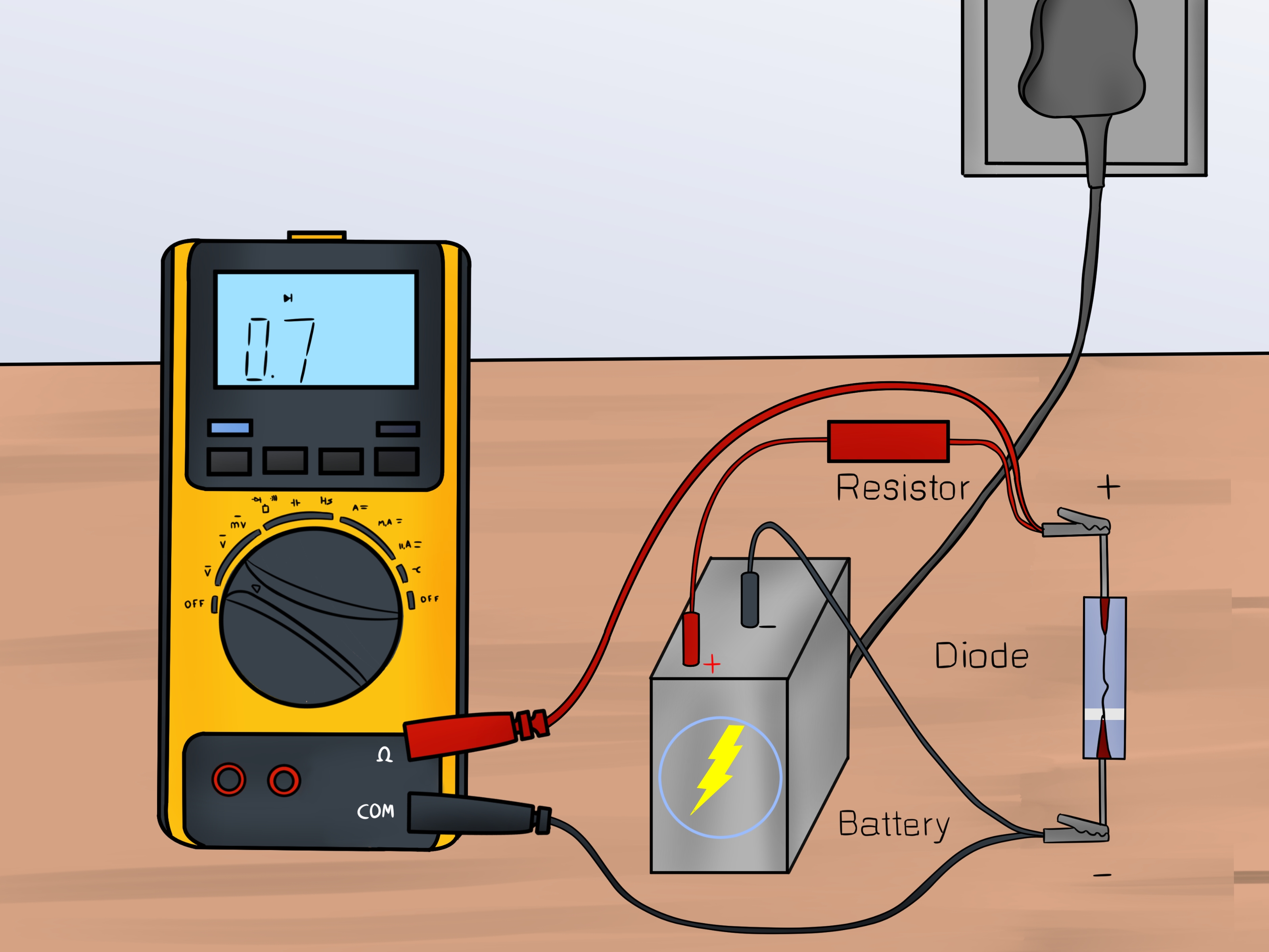
The diode test setting is the best first choice on a digital multimeter. It is usually marked with a diode symbol, which looks like a little triangle pointing at a vertical line. In this mode, the meter sends a small test current through the diode and displays the forward voltage drop.
For a common silicon diode, the forward voltage reading is often around 0.5 to 0.8 volts. Many people casually say “about 0.7 V,” and that is a useful rule of thumb, but do not treat it like the Ten Commandments carved into a bench power supply. The exact reading depends on the diode type, test current, temperature, and the meter itself. A 1N4148 switching diode and a 1N4007 rectifier diode can both be good while showing slightly different values.
Step-by-step diode mode test
- Turn the multimeter dial to diode test mode.
- Touch the red probe to the anode side of the diode.
- Touch the black probe to the cathode side, usually the striped end.
- Read the display. A healthy silicon diode usually shows a forward voltage drop, commonly near 0.6–0.7 V.
- Reverse the probes: red probe to cathode, black probe to anode.
- Read the display again. A good diode should show OL, “1,” or another over-range indication, meaning it is blocking current.
How to understand diode mode results
| Meter Reading | Likely Meaning |
|---|---|
| 0.5–0.8 V forward, OL reverse | Usually a good silicon diode |
| 0.000 V or very low both ways | Likely shorted diode |
| OL both ways | Likely open diode, wrong contact, or meter cannot forward-bias it |
| Similar reading both ways | Possibly bad diode or misleading in-circuit reading |
| Higher or lower than expected | May be a different diode type, temperature effect, or circuit influence |
Diode mode is especially helpful because it gives you a meaningful voltage number instead of a vague resistance value. If your silicon diode reads 0.64 V in one direction and OL in the other, it is probably doing its one job with admirable commitment.
Method 2: Test the Diode with Resistance Mode
If your multimeter does not have diode mode, resistance mode can still give you useful clues. This old-school method checks whether the diode shows lower resistance in the forward direction and much higher resistance in the reverse direction.
Set the meter to an ohms range. If your meter is auto-ranging, just select Ω. If it is manual-ranging, choose a higher range such as 2 kΩ, 20 kΩ, or 200 kΩ and adjust if needed. Place the red probe on the anode and the black probe on the cathode. A good silicon diode should show some measurable resistance in the forward direction. Then reverse the probes. The reverse reading should be much higher, often over-range or OL.
Why resistance mode is less precise
Resistance mode was not designed specifically for diodes. A diode is nonlinear, which means its apparent resistance changes depending on the test voltage and current. One meter may show a few hundred ohms, another may show several kilo-ohms, and both meters may be behaving normally. This is why you should not judge a silicon diode by a single resistance number alone.
Instead, compare the two directions. A healthy diode normally conducts better one way than the other. If it reads nearly zero ohms both ways, it is probably shorted. If it reads OL both ways, it may be open, poorly contacted, or not receiving enough test voltage from that resistance range. If the two readings are strangely similar, the diode may be faulty, or it may still be connected to other components that are creating an alternate path.
Resistance mode example
Suppose you test a small silicon diode out of circuit. In one direction, your meter shows 1.2 kΩ. When you reverse the probes, it shows OL. That is a strong sign the diode is working. Now suppose another diode shows 4 Ω forward and 4 Ω reverse. That diode is not being mysterious; it is probably shorted. Finally, if a diode shows OL in both directions, inspect the leads, clean oxidation from the contact points, and test again. If the result remains the same, the diode may be open.
Resistance mode is not as elegant as diode mode, but it is handy when you are using a simple meter. Think of it as the pocket flashlight of diode testing. It may not illuminate the whole laboratory, but it can keep you from walking into the furniture.
Method 3: Test the Diode In-Circuit with a Low-Voltage Check
Sometimes you cannot remove the diode easily. Maybe it is soldered into a crowded circuit board, or maybe your soldering iron is hiding somewhere under three cables and a suspiciously permanent pile of “temporary” parts. In-circuit testing can help, but it requires caution because nearby resistors, coils, capacitors, IC pins, and parallel paths can affect the reading.
Start with power off. Use diode mode and test the diode in both directions just as you would out of circuit. If the reading looks normal, the diode may be fine. If the reading looks shorted or strange, do not immediately sentence the diode to the trash bin. Another component may be connected across it. This is common in protection circuits, relay coils, bridge rectifiers, and power input sections.
The one-lead rule
When in-circuit results are confusing, lift one diode lead from the board and test again. Desoldering only one side isolates the diode enough for a much more reliable reading. This simple move prevents many false diagnoses. It also saves you from replacing a perfectly good diode and then discovering the real problem was a shorted capacitor nearby. Electronics troubleshooting is humbling like that.
Optional live voltage check for low-voltage circuits
For battery-powered or other low-voltage DC circuits, an experienced hobbyist may also measure voltage across the diode while the circuit is operating. Set the meter to DC volts, connect the probes across the diode, and observe the voltage drop under real operating conditions. A forward-biased silicon diode may show a drop near the expected forward-voltage range. A reverse-biased diode may show a higher circuit voltage across it because it is blocking current.
This live test should only be used on safe, low-voltage circuits you understand. Do not use it on household AC, high-voltage power supplies, large appliances, or unknown equipment. For many repairs, the safer powered-off diode mode test plus the one-lead rule is enough.
Common Mistakes When Testing Silicon Diodes
Mistake 1: Testing in-circuit and trusting the first reading
A diode connected to other parts of a circuit can produce confusing results. If the meter shows conduction both ways, the diode may be bad, but it may also be sitting across a transformer winding, resistor, transistor junction, or protection network. Confirm by lifting one lead.
Mistake 2: Confusing continuity mode with diode mode
Continuity mode is designed to beep when resistance is low. It is useful for checking wires and fuses, but it is not a complete diode test. Some meters combine continuity and diode mode on the same dial position, while others do not. A beep alone does not tell you the forward voltage drop, so do not let the multimeter chirp you into overconfidence.
Mistake 3: Expecting every diode to read exactly 0.700 V
Silicon diodes vary. Small-signal diodes, rectifier diodes, fast recovery diodes, and protection diodes may not show identical readings. Temperature also matters. A warm silicon junction usually shows a lower forward voltage than a cold one. If your diode reads 0.58 V or 0.72 V, that may be perfectly normal.
Mistake 4: Ignoring polarity markings
The stripe marks the cathode on many common diodes. On a circuit board, the silkscreen may also show a diode symbol or a band marking. Read the part and the board carefully. Guessing polarity is a little like assembling furniture without looking at the instructions: possible, but emotionally expensive.
How to Tell If a Silicon Diode Is Bad
A bad diode often reveals itself clearly. A shorted diode conducts in both directions and may show a very low reading either way. This can blow fuses, drag down power rails, overheat resistors, or make a power supply behave like it woke up on the wrong side of the schematic.
An open diode does not conduct in either direction. In diode mode, the meter may show OL both ways. This can prevent rectification, stop a protection path from working, or break a signal route.
A leaky diode is trickier. It may pass the basic diode test but fail under real circuit voltage or temperature. If a circuit acts strangely after the diode passes a simple test, compare it with a known-good diode of the same type, check the datasheet, or test under controlled circuit conditions. Basic multimeter testing is powerful, but it is not a full semiconductor lab in your hand.
Practical Examples
Example 1: Testing a 1N4007 rectifier diode
Set the multimeter to diode mode. Place the red probe on the anode and the black probe on the striped cathode end. If the display reads around 0.6 V and shows OL when the probes are reversed, the diode is likely good. This is the classic textbook result, the electronics equivalent of a clean bill of health and a polite handshake.
Example 2: Testing a diode on a circuit board
You test a diode in-circuit and get 0.21 V one way and 0.24 V the other way. That looks suspicious, but it does not automatically mean the diode has failed. A parallel component may be affecting the reading. Lift one lead of the diode and retest. If it then reads 0.65 V forward and OL reverse, the diode was innocent. Apologize silently and continue troubleshooting.
Example 3: Finding a shorted protection diode
A battery-powered device will not turn on, and the input terminals show very low resistance. You find a reverse-polarity protection diode across the input. In diode mode, it reads nearly zero volts both directions. After removing one lead, it still reads shorted. That diode has likely failed and may be clamping the supply. Replacing it with the correct type can restore normal operation, assuming nothing else was damaged.
Experience Notes: What Real Diode Testing Teaches You at the Workbench
After you test enough silicon diodes, you start to learn that the multimeter is not just giving numbers; it is telling a story. The first lesson is that a clean, out-of-circuit test is almost always easier to trust. When a diode is sitting by itself on the bench, the reading is usually simple: forward voltage one way, OL the other. When that same diode is soldered into a crowded board, the reading can become a soap opera. Suddenly you are not testing one component anymore. You are testing the diode, two resistors, a capacitor that still has opinions, and maybe an IC input protection path hiding in the background.
One practical habit is to write down the first reading before changing anything. For example, if a silicon diode reads 0.63 V forward and OL reverse, note it. If another identical diode on the same board reads 0.63 V forward and 0.64 V reverse, that second result deserves attention. Comparison is one of the best troubleshooting tools you have, especially on boards with repeated channels, such as audio amplifiers, LED drivers, power supplies, and motor controllers. Identical sections should usually behave similarly. When one section acts different, it is waving a tiny electronic flag.
Another useful experience is learning not to panic over slight variation. A diode reading of 0.59 V is not automatically better or worse than 0.68 V. Meter models differ, test currents differ, and temperature can shift the forward voltage. If you hold a small diode between your fingers for a while, body heat may slightly change the reading. That does not mean the diode has developed a personality problem. It means semiconductor junctions are affected by temperature, which is normal.
The “one-lead rule” becomes more valuable the longer you troubleshoot. Many beginners replace parts based only on in-circuit readings, then feel personally betrayed when the device still does not work. Lifting one leg of the diode takes a little extra time, but it can prevent unnecessary part swapping. In repair work, guessing is expensive. Confirming is cheaper, calmer, and less likely to create new problems.
Good probe technique also matters. Oxidized leads, dirty component legs, solder flux, and shaky hands can all produce unstable readings. Press firmly, use sharp probe tips when needed, and test the meter leads by touching them together before blaming the component. A surprising number of “bad diode” mysteries begin with a loose probe connection. The diode was fine; the human interface needed debugging.
Finally, always consider the job the diode performs in the circuit. A rectifier diode in a power supply, a flyback diode across a relay coil, and a small signal diode in a logic circuit may all be silicon diodes, but they live very different lives. If a replacement is needed, match the important specifications, including voltage rating, current rating, switching speed, package style, and polarity. A diode is small, but putting in the wrong one can turn a simple repair into a sequel nobody asked for.
Conclusion
Learning how to test a silicon diode with a multimeter is one of the most useful electronics skills you can pick up. Use diode mode first because it directly shows forward voltage drop. Use resistance mode when your meter does not have diode mode. Use in-circuit testing carefully, and when the results look suspicious, isolate one lead before making a final call.
A healthy silicon diode usually conducts in the forward direction and blocks in reverse. A shorted diode conducts both ways. An open diode conducts neither way. A confusing diode may simply be surrounded by other components that are photobombing your measurement. With a patient method, clean probe contact, and a little suspicion toward in-circuit readings, you can test diodes confidently without turning your workbench into a guessing game.