Note: This article is written as original educational content for web publishing, based on real small-batch electronics practices, documented badge projects, maker-marketplace history, and practical PCB assembly workflows.
Introduction: When a Tiny Badge Becomes a Real Engineering Lesson
At first glance, an electronic badge looks like a cute little piece of conference swag. It blinks, hangs from a lanyard, makes hardware people smile, and occasionally convinces someone to pull a soldering iron out of a backpack like a magician producing a rabbit. But behind that glowing PCB face is a surprisingly serious engineering question: how do you build something fun, reliable, attractive, and affordable when every cent matters?
That is where BOM cost optimization enters the room, wearing safety glasses and carrying a spreadsheet. BOM stands for bill of materials, the complete list of parts needed to manufacture a product. In badge engineering, the BOM can include the printed circuit board, LEDs, coin-cell battery holder, switch, resistors, microcontroller, connectors, pin clasp, packaging, and sometimes even stickers, bags, and assembly instructions. On a one-off art project, a few extra cents may not matter. On a run of 300, 1,000, or 2,000 badges, those cents form a tiny army and march directly into your budget.
The Tindie badge story is a great case study because it lives at the intersection of open hardware culture, small-batch manufacturing, PCB art, and practical cost control. Tindie has long been associated with independent hardware makers selling clever electronics directly to enthusiasts. A badge made for that audience cannot simply be cheap; it has to feel maker-worthy. It needs personality, solderability, durability, and just enough sparkle to make someone say, “I need one,” preferably before asking, “Wait, where did my coin cell go?”
What BOM Cost Optimization Really Means
BOM cost optimization is not just “buy cheaper parts.” That approach is how projects end up with switches that feel like soggy cereal and battery holders that release cells at the worst possible moment. Real optimization means balancing cost, function, availability, manufacturability, assembly time, reliability, and user experience.
For a simple electronic badge, the BOM may appear harmless. Two LEDs, a battery, a holder, a switch, a PCB, and a pin back: how expensive can that be? The answer depends on quantity, sourcing, board design, packaging, and labor. A component that costs $0.18 instead of $0.30 sounds like pocket lint until you multiply it across thousands of units. A board outline that wastes panel space can quietly raise fabrication cost. A part that is cheap but difficult to solder may increase support issues, failed kits, and sad faces at the workshop table.
The goal is not to remove joy from the design. The goal is to spend money where users notice it and stop spending money where only the spreadsheet notices it. In badge engineering, users notice brightness, artwork, ease of assembly, battery life, and whether the badge survives being tossed into a backpack next to keys, adapters, and one mysterious USB cable from 2009.
The Tindie Badge as a Small-Batch Hardware Case Study
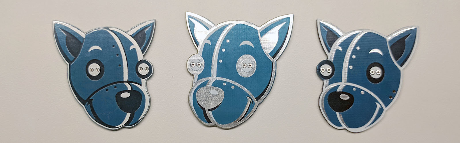
The documented Tindie blinky badge evolved through several revisions, with cost reductions achieved through quantity changes and targeted component decisions. The early version used a simple formula: a custom PCB shaped as the Tindie mascot, flashing RGB LEDs, a coin-cell battery, a battery holder, and a pin clasp. That is wonderfully minimal, which is exactly why it is useful as an engineering example.
In the first run, the project moved fast. A few hundred badges were designed, ordered, kitted, and distributed in a short window. The first version proved the concept: people liked the badge, it was portable, and it represented the maker-marketplace spirit better than another pile of paper flyers. But the first version also revealed the classic truth of hardware: the first build teaches you what the spreadsheet forgot to mention.
Later revisions improved both aesthetics and cost. The design used PCB layers as artwork: copper, solder mask, silkscreen, and exposed metal became part of the visual language. This is one of the joys of badge engineering. A PCB is not merely a green rectangle that reluctantly carries electrons. It can be the product, the enclosure, the artwork, and the brand identity all at once.
Why Small Changes Matter
In a badge project, a revision may not require a grand reinvention. Sometimes the smartest engineering decision is switching a holder, changing the component placement, using a more common switch, or adjusting the board finish so the art reads more clearly. The best cost reductions usually come from understanding the design deeply enough to know which parts are sacred and which parts are negotiable.
For the Tindie-style badge, the LEDs were part of the charm. Remove the blinking eyes and the badge becomes a quiet piece of fiberglass with identity issues. The PCB shape and artwork were also central. But components such as the switch and battery holder were fair targets for value engineering, because users care that they work; they usually do not care which supplier’s catalog page they came from.
Engineering the Badge: Cost, Art, and Soldering Reality
A good electronic badge has three jobs. First, it must look good from a few feet away. Second, it must work electrically. Third, it must survive human behavior, which is always the harshest test standard. People will wear it, drop it, poke it, solder it badly, reverse the LED, forget the battery, and then blame the badge with confidence.
That is why badge engineering should begin with the user journey. Is this a fully assembled badge, a soldering kit, or both? Is it for beginners? Will it be built at a conference table with questionable lighting and a line of impatient hackers behind the builder? These questions shape the BOM. Through-hole LEDs are friendly for soldering kits. Surface-mount parts reduce size and can improve production efficiency, but they may intimidate beginners. Coin cells keep the badge slim, while AAA battery packs may provide longer life but add bulk and cost.
PCB Art as a Cost Feature
PCB art is not just decoration; it can reduce the need for separate enclosures, labels, and cosmetic parts. By using copper, solder mask, silkscreen, bare substrate, and plated finishes creatively, the board itself becomes the finished product. That is especially powerful for badges, where the circuit board is meant to be seen.
However, artwork has manufacturing consequences. Fine silkscreen details can blur. Exposed copper may change finish cost. Odd board shapes may reduce panel efficiency. Large cutouts, internal slots, and unusual outlines can raise fabrication complexity. The trick is to design art that cooperates with the factory instead of making the factory sigh loudly.
Where the Money Goes in a Badge BOM
A badge BOM looks simple, but the cost stack has layers. The obvious costs are components and PCB fabrication. The sneaky costs are sourcing, shipping, packaging, kitting, scrap, assembly time, test fixtures, and support.
1. Printed Circuit Board
The PCB may be both the largest physical part and the visual centerpiece. Cost depends on board area, layer count, finish, solder mask color, panel utilization, routing complexity, and quantity. A two-layer board is usually the practical choice for a simple blinky badge. Four layers may be justified for complex badges with RF, displays, audio, or dense microcontrollers, but for a basic LED badge, four layers are like renting a moving truck to carry a sandwich.
2. LEDs and Visual Components
LEDs are cheap, but they define the badge’s personality. Flashing RGB LEDs can provide animation without a microcontroller, reducing firmware complexity and component count. Addressable LEDs offer spectacular effects, but they require control circuitry, power planning, and sometimes level shifting. The right choice depends on whether the badge is a giveaway, a kit, a collectible, or a tiny nightclub for engineers.
3. Battery and Holder
Battery strategy is a major BOM decision. Coin cells are compact and badge-friendly. CR2032 cells are common and easy to source; smaller coin cells can save space but may offer less capacity. The holder matters too. A cheap holder that loses contact can make a good badge seem broken. A slightly better holder may save far more than it costs by reducing failures, returns, and conference-table troubleshooting.
4. Switches
A switch is a tiny part with a big job. Without it, users must remove the battery to turn the badge off, which is annoying and increases the chance of losing the cell. Adding a switch raises BOM cost but improves usability. Optimizing the switch means finding a part that is affordable, available, solderable, durable, and not so tiny that beginners need tweezers, prayer, and a microscope.
5. Packaging and Kitting
Packaging often receives less attention than components, but it matters. A bag, instruction card, sticker, battery warning, and sorted parts can change the user experience dramatically. Good kitting reduces confusion. Bad kitting creates a support line in human form, usually standing next to your booth holding two resistors and a haunted expression.
Practical BOM Cost Optimization Strategies
Standardize Parts Across Revisions
Using the same LEDs, resistors, switches, or holders across multiple badge versions increases purchasing leverage and reduces sourcing complexity. It also simplifies documentation and assembly. If the badge family grows, common components become a quiet superpower.
Design Around Available Parts
Never fall in love with a component that is rare, backordered, or available only from one mysterious supplier with a website last updated during the dial-up era. Good badge engineering begins with availability checks. Distributor BOM tools can help validate part numbers, pricing, alternates, and stock before the design is frozen.
Use Alternate Parts Intelligently
A professional BOM should include approved alternates where possible. For a resistor, alternates are easy. For a switch or battery holder, alternates require footprint compatibility and mechanical review. For LEDs, brightness, viewing angle, color, and forward voltage can affect the final appearance. “Equivalent” does not always mean “looks the same when worn in a dim hotel ballroom.”
Reduce Unique Line Items
Every unique part adds sourcing, counting, placement, and error risk. A badge with three resistor values may be technically fine, but one value is easier for kitting and assembly. If two LEDs can share a resistor value safely, do it. If one screw size works everywhere, use one screw size. The BOM should not feel like a scavenger hunt.
Optimize the PCB Panel
Board outline affects panelization. A badge shaped like a mascot may be adorable, but if it wastes panel space, the cost rises. Designers can sometimes nest shapes, adjust tabs, or slightly modify outlines to fit more units per panel. The best badge shape is one that looks intentional to humans and efficient to manufacturing software.
Plan for Testing
Testing is part of cost optimization. A badge that is hard to test can waste labor. Add test pads when needed. Make battery polarity obvious. Label LEDs clearly. Include a simple power check. If the badge is a kit, design the instructions so a beginner can self-diagnose common mistakes without summoning an engineer from lunch.
Specific Example: A Simple Blinky Badge BOM
Imagine a simple Tindie-inspired blinky badge with two flashing RGB LEDs, one coin-cell holder, one slide switch, one CR2032 battery, one custom two-layer PCB, and one pin back. The first cost review should separate “identity parts” from “commodity parts.” The PCB shape and LEDs create the emotional value. The battery holder and switch provide function. The pin back and bag support wearability and delivery.
If the badge costs too much, do not immediately shrink the board until the art looks sad. First check whether the holder has a lower-cost footprint-compatible option. Review switch pricing at the intended quantity. Compare battery sourcing. Ask whether packaging can be simplified without making the kit feel cheap. Check whether ordering 1,000 instead of 300 changes pricing enough to justify a larger run. Sometimes the cheapest unit cost creates the most expensive storage problem, so be realistic.
Common Mistakes in Badge BOM Optimization
Choosing the Cheapest Part Without Testing It
The lowest unit price can be a trap wearing a discount sticker. Always build samples with the actual part. A battery holder that looks fine in a catalog may have poor retention. A switch may feel fragile. An LED may be too dim. Real hardware has a talent for embarrassing assumptions.
Ignoring Assembly Labor
A cheaper part that takes longer to solder may not be cheaper. Through-hole parts are beginner-friendly but can be slower in production. Surface-mount parts suit assembly lines but may be harder for workshops. The right decision depends on whether the badge is sold assembled, sold as a kit, or handed out as an activity.
Forgetting Documentation
Documentation is part of the product. Clear polarity marks, assembly drawings, and short instructions reduce failed builds. A well-designed badge kit should make the builder feel clever, not trapped in a tiny electronics escape room.
The Business Side: Tindie, Makers, and Small-Batch Reality
Tindie-style hardware sits in a special market. Makers often build in small batches, test demand quickly, and iterate based on feedback. Unlike mass-market consumer electronics, a badge may sell in dozens, hundreds, or a few thousand units. That scale rewards practical design. You cannot always negotiate like a giant manufacturer, so you win through clever sourcing, simple assembly, reusable design blocks, and honest pricing.
A badge also carries brand value. A memorable electronic badge can promote a marketplace, conference, workshop, or community better than a disposable flyer. People keep good badges. They show them online. They trade them. They modify them. In that sense, the BOM is not just a cost document; it is a strategy document for delight.
of Practical Experience: Lessons From Badge Engineering in the Real World
The first experience every badge designer eventually earns is this: the BOM is never finished when you think it is finished. It looks complete in the spreadsheet, the schematic passes inspection, the board render looks gorgeous, and then someone asks, “Do we have batteries?” Suddenly the project manager ages three years. Batteries, bags, labels, tape, headers, spare LEDs, and test fixtures are easy to forget because they are not glamorous. Yet they are the parts that decide whether the badge arrives as a delightful kit or a loose handful of confusion.
A second practical lesson is that component placement is user experience. On a badge, the battery holder should not fight the pin clasp. The switch should be reachable when the badge is being worn. LEDs should shine where the artwork expects them to shine. If the board is meant for beginners, polarity markings should be large enough to see without a jeweler’s loupe. The best badge layout feels obvious. The builder should not need to decode the silkscreen like an ancient map.
Third, always build a pilot batch. Not one prototype. A small batch. A single prototype tells you whether the circuit can work. A pilot batch tells you whether the design can be manufactured, assembled, packed, and explained repeatedly without everyone losing their sparkle. Build ten or twenty. Hand them to people who did not design them. Watch where they hesitate. Watch which part they install backward. Watch whether the switch survives being clicked by someone with the enthusiasm of a caffeinated woodpecker.
Fourth, treat sourcing as engineering, not shopping. When a badge depends on one exact switch from one supplier, the design has a hidden risk. If that switch disappears, your schedule disappears with it. Add alternate parts early. Use footprints that can accept more than one compatible component when reasonable. Keep a source column, manufacturer part number, distributor part number, lifecycle status, and approved alternate column in the BOM. This sounds boring until it saves the project three days before production.
Fifth, do not optimize away the soul. Cost reduction is necessary, but a badge is not a medical device enclosure or a beige office router. It is meant to be noticed. If the blinking eyes, clever board shape, beautiful solder mask contrast, or playful kit experience is what makes people love it, protect that feature. Cut cost from invisible waste, not visible joy. Reduce redundant line items. Improve panel efficiency. Choose better quantity breaks. Simplify packaging. But keep the moment when someone powers it on and grins.
Finally, write down what changed between revisions. Badge projects often move quickly, especially around conferences. Without revision notes, the team may forget why a part changed, why a footprint grew, or why a resistor value was selected. A clean changelog turns chaos into engineering memory. That memory is how a one-time badge becomes a repeatable product, and how a fun giveaway becomes a small-batch hardware lesson worth sharing.
Conclusion: The Badge Is Small, but the Engineering Is Not
BOM cost optimization and Tindie badge engineering prove that small hardware can teach big lessons. A simple blinking badge touches design for manufacturability, sourcing, PCB art, user experience, testing, packaging, and community identity. The best badges are not merely cheap; they are intelligently economical. They put cost where it creates delight and remove cost where it only creates waste.
For makers, startups, conference organizers, and hardware sellers, the lesson is clear: build the BOM early, revise it honestly, test real parts, and respect the builder. A badge may be tiny, but it contains the same pressures as larger electronics projects. It has deadlines, budgets, supply constraints, assembly decisions, and customers who expect it to work. The only difference is that this product also gets to blink at people, which frankly makes it more charming than most spreadsheets.