Engineering drawings can look intimidating at first glance. Lines run everywhere, numbers huddle in corners, symbols appear as if someone spilled a keyboard onto the page, and the title block quietly judges you from the bottom right. But once you understand the logic, an engineering drawing becomes less like a secret code and more like a very serious recipe: follow the instructions, respect the tolerances, and do not “eyeball it” unless you enjoy expensive mistakes.
This guide explains four practical ways to read engineering drawings with confidence. Whether you are a student, machinist, fabricator, inspector, designer, technician, or curious human who has been handed a blueprint and asked to “just check this real quick,” these methods will help you understand what the drawing is saying before metal is cut, plastic is molded, concrete is poured, or parts are assembled.
The main goal of reading engineering drawings is simple: understand the design intent. A drawing is not only a picture of a part. It is a contract between design, manufacturing, quality control, purchasing, and assembly. Every view, dimension, note, tolerance, symbol, and revision exists to prevent confusion. Of course, confusion still shows up wearing safety glassesbut a good reader knows how to chase it away.
Why Engineering Drawings Matter
Engineering drawings, also called technical drawings or blueprints, communicate how something should be made, measured, inspected, and assembled. They may describe a single machined bracket, a welded frame, a circuit enclosure, a building component, or a complex mechanical assembly. Even when a 3D CAD model exists, the 2D engineering drawing remains essential because it captures information that a model alone may not clearly define: tolerances, materials, finishes, inspection requirements, revision history, notes, and special manufacturing instructions.
A well-prepared drawing answers practical questions: What is the part? What material should be used? What size should each feature be? Which dimensions are critical? What variation is acceptable? Which surface needs finishing? What is the latest revision? What standard applies? What view shows the hidden feature? In other words, it saves everyone from playing the world’s least enjoyable guessing game.
1. Start With the Title Block, Notes, and Revision History
The first way to read engineering drawings is to begin where many beginners end: the title block. It is usually located in the lower-right corner of the sheet, and it contains the drawing’s identity card. Before studying the shape of the part, read the title block carefully. It tells you what drawing you are looking at, who created it, what revision is current, what units are used, what scale applies, and sometimes what default tolerances control unspecified dimensions.
What to Look for in the Title Block
A typical title block may include the part name, drawing number, company name, designer, checker, approver, sheet size, scale, projection method, revision level, material, finish, and general tolerance block. These details are not decoration. If the drawing number is wrong, the revision is outdated, or the units are misunderstood, everything that follows can go sideways quickly.
For example, imagine reading a drawing and assuming all dimensions are in inches when the title block clearly states millimeters. Congratulations: your part may now be either tiny, gigantic, or suitable only as modern art. Always confirm the units before reading dimensions. In U.S. manufacturing, drawings may use inches or metric units depending on the company, industry, and project. The title block settles the debate.
Check the Revision Before Trusting the Drawing
Revision history shows whether the drawing has changed. It may list revision letters or numbers, dates, descriptions of changes, and approval signatures. This is especially important in manufacturing and quality inspection because older drawings may contain dimensions, materials, or tolerances that are no longer valid.
If a drawing has Revision C but the purchase order, CAD model, or production traveler references Revision D, stop and clarify before making the part. In engineering, “close enough” can become “scrap enough” very quickly. A tiny change to a hole location or material specification may affect assembly, strength, performance, or safety.
Read General Notes Like They Owe You Money
General notes often appear near the title block or on a separate notes area. These notes may specify deburring requirements, edge breaks, surface finish, heat treatment, plating, welding standards, inspection methods, cleaning requirements, or packaging instructions. A dimensioned view may tell you the part’s shape, but the notes often tell you how the part must behave, feel, fit, or survive in service.
Common examples include “Remove all burrs,” “Break sharp edges,” “Unless otherwise specified, dimensions are in inches,” or “Surface finish 125 microinch Ra maximum.” These statements may look small, but they can decide whether a part passes inspection or causes assembly workers to mutter colorful phrases under their breath.
2. Understand the Views, Projection Method, and Drawing Layout
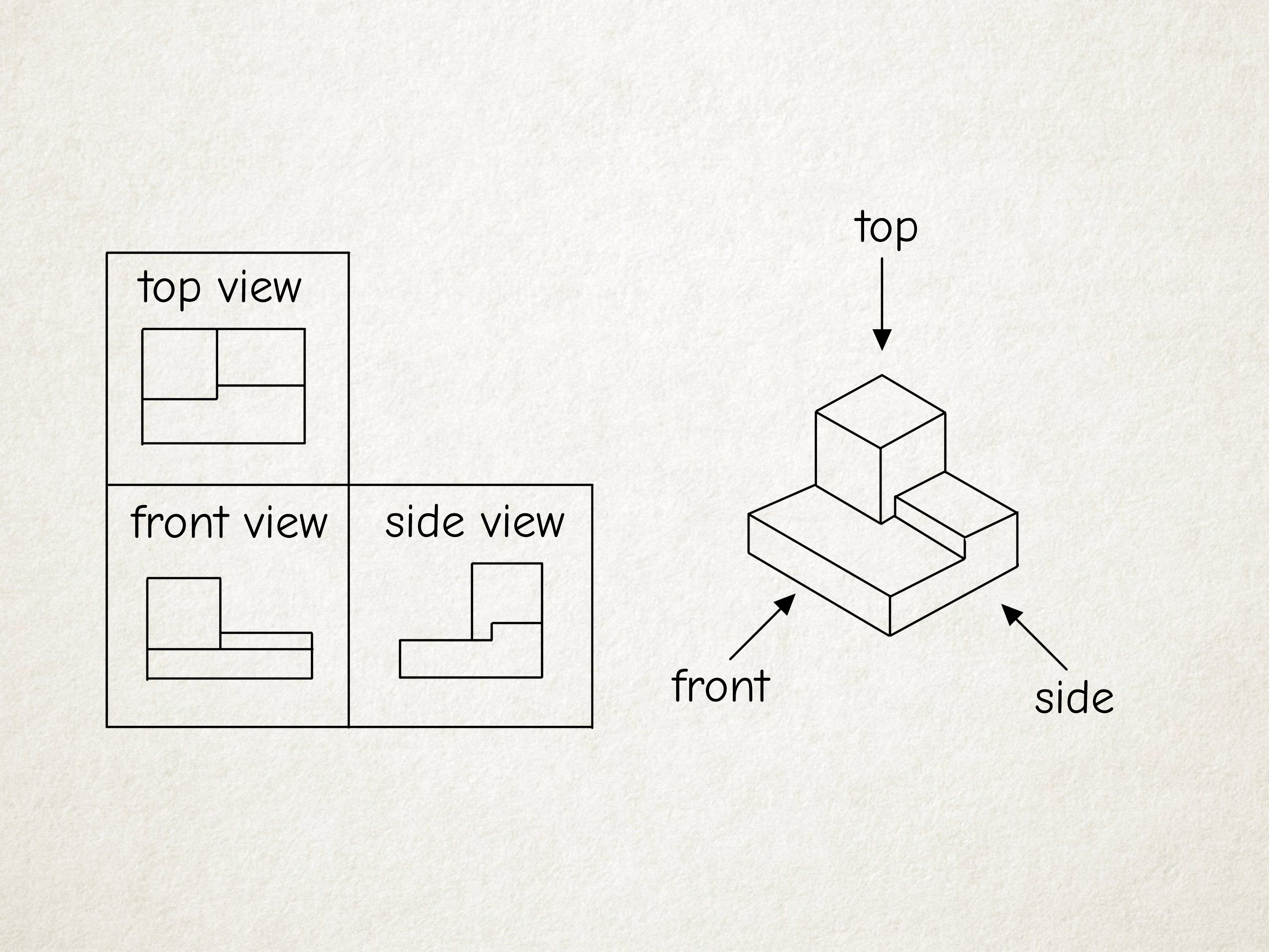
The second way to read engineering drawings is to understand how the object is represented. Most engineering drawings use orthographic projection, which shows different sides of a 3D object as flat 2D views. Typical views include front, top, right side, left side, bottom, rear, section, detail, auxiliary, and isometric views.
Orthographic Views: The Part From Different Angles
An orthographic drawing does not show the part the way your eye naturally sees it. Instead, it separates the object into clear, measurable views. The front view may show height and width. The top view may show width and depth. The right-side view may show height and depth. Together, these views create a complete description of the object.
When reading these views, do not treat them as separate drawings. They are connected. A hole visible in the front view should align with its location in the top or side view. A slot shown in one view may be dimensioned in another. Hidden lines may indicate internal features that are not visible from the outside. Centerlines usually mark the axes of holes, cylinders, arcs, and symmetrical features.
First-Angle vs. Third-Angle Projection
Projection method matters. In the United States, third-angle projection is commonly used. In third-angle projection, the top view is placed above the front view, and the right-side view is placed to the right of the front view. In first-angle projection, commonly used in some other regions, the arrangement is reversed in a way that can confuse readers who are not paying attention.
The projection symbol in the title block tells you which method applies. Never assume. Misreading projection can cause features to be interpreted on the wrong side of a part. That is the kind of mistake that does not merely create confusionit creates phone calls, rework, and possibly a manager doing the long silent stare.
Section Views and Detail Views
Section views show what the part looks like if it were cut through a specific plane. They are extremely useful for internal features such as holes, cavities, ribs, walls, grooves, and assemblies. A cutting-plane line usually identifies where the section is taken, and arrows show the viewing direction.
Detail views enlarge a small area of the part so tiny features can be shown clearly. If a drawing has a detail circle labeled “Detail A,” find the enlarged Detail A view and read the dimensions there. Do not rely on the smaller main view for features that are intentionally magnified elsewhere.
Isometric Views Are Helpful, But Not Always Controlling
Isometric views show the part in a 3D-like orientation, often making the geometry easier to understand. They are excellent for visualization, especially on complex parts. However, dimensions are usually controlled by orthographic views, section views, detail views, and notes. Treat the isometric view as a helpful map, not the full legal document.
3. Read Dimensions, Tolerances, and Scale Correctly
The third way to read engineering drawings is to study the dimensions and tolerances. Dimensions tell you the intended size and location of features. Tolerances tell you how much variation is allowed. Together, they define whether a finished part is acceptable.
Basic Dimension Types
Linear dimensions define length, width, height, depth, thickness, and spacing. Angular dimensions define angles. Diameter dimensions use the diameter symbol to specify round features such as holes and shafts. Radius dimensions define arcs and rounded corners. Depth symbols may be used for blind holes. Countersink and counterbore symbols describe special hole shapes used for screws, bolts, and fasteners.
For example, a hole callout might specify a diameter, a depth, and a tolerance. If the callout says a hole is 0.250 inches in diameter with a tolerance of plus or minus 0.005 inches, then an acceptable hole size would range from 0.245 to 0.255 inches. That may sound simple, but on a busy drawing, the trick is knowing which tolerance applies to which feature.
General Tolerances vs. Specific Tolerances
Many drawings include general tolerances in the title block. These apply when a dimension does not have its own specific tolerance. For instance, the title block might state that two-place decimal dimensions have a tolerance of plus or minus 0.01 inch, while three-place decimal dimensions have a tolerance of plus or minus 0.005 inch.
Specific tolerances override general tolerances. If a dimension is individually marked as 1.000 plus or minus 0.002, use that tolerance, not the default title block tolerance. This matters because tighter tolerances usually increase manufacturing difficulty, inspection time, and cost. A good drawing does not make every dimension ultra-tight just to look impressive. That is not precision; that is wallet aerobics.
Do Not Scale the Drawing Unless Told to Do So
The scale listed in the title block tells how the printed view relates to the actual object. However, modern engineering practice generally discourages measuring directly from a printed drawing unless a scale bar or specific instruction allows it. Printed sheets can be resized, scanned, stretched, or displayed on screens at unpredictable zoom levels.
Use the written dimensions, not a ruler on the screen. The drawing scale helps with visualization, but the dimension values control the part. If a printed line looks like 2 inches but the dimension says 2.125 inches, the dimension wins. The line can complain all it wants.
Avoid Dimension Traps
Several common mistakes happen when reading dimensions. One is ignoring hidden dimensions in other views. Another is double-counting chained dimensions. A third is assuming symmetry when the drawing does not explicitly define it. Also watch for reference dimensions, often shown in parentheses. Reference dimensions are informational and usually not used for manufacturing acceptance.
When dimensions are chained from one feature to the next, tolerance accumulation can become important. If every segment has its own tolerance, the final location may vary more than expected. Baseline dimensions, coordinate dimensions, or GD&T position controls can help reduce ambiguity. As a reader, your job is to recognize how the drawing controls feature locationnot just collect numbers like they are trading cards.
4. Decode Symbols, GD&T, Materials, and Manufacturing Notes
The fourth way to read engineering drawings is to interpret the symbolic language. Engineering drawings use symbols to communicate complex requirements efficiently. These may include surface finish symbols, welding symbols, datum references, geometric tolerancing frames, thread callouts, material specifications, finish notes, and inspection requirements.
GD&T: The Grammar of Precision
GD&T stands for Geometric Dimensioning and Tolerancing. It is a standardized system used to describe allowable variation in form, orientation, location, and runout. Instead of only saying how large a feature should be, GD&T explains how that feature must relate to other features.
Common GD&T controls include flatness, straightness, circularity, cylindricity, perpendicularity, parallelism, angularity, position, concentricity, symmetry, circular runout, and total runout. A feature control frame may include a geometric symbol, tolerance value, material condition modifier, and datum references. It looks compact because it is doing a lot of work.
For example, a positional tolerance may control how far the center of a hole can deviate from its theoretically exact location relative to datums A, B, and C. This is much clearer than relying on several plus-or-minus coordinate dimensions that may not fully describe functional fit. In practical terms, GD&T helps manufacturers and inspectors understand what matters most for the part to work.
Datums Are Your Reference Anchors
A datum is a reference feature, such as a flat surface, hole axis, or center plane, used to establish measurement relationships. Datum labels such as A, B, and C identify the order and function of these references. When reading GD&T, always find the datums before interpreting the tolerance frame. Without datums, many geometric controls are like directions that say “turn left” without telling you where you are.
Material and Finish Requirements
The material note tells what the part should be made from, such as aluminum alloy, stainless steel, carbon steel, plastic, brass, or another specified material. It may include a grade, standard, temper, hardness, or heat-treatment condition. The finish note may call for anodizing, plating, painting, passivation, powder coating, polishing, or a required surface roughness.
Do not treat material and finish as afterthoughts. A part made from the wrong material may have the right dimensions and still fail in use. A surface left too rough may cause friction, leakage, wear, poor sealing, or cosmetic rejection. A coating may change final dimensions, especially on tight-fitting features. If the drawing specifies a finish after machining, consider whether the dimensions apply before or after finishing.
Thread, Hole, and Fastener Callouts
Thread callouts specify threaded features, including nominal size, thread pitch or threads per inch, class of fit, depth, and sometimes thread series. Hole callouts may define drilled holes, reamed holes, tapped holes, counterbores, countersinks, spotfaces, or clearance holes. These callouts are small but powerful. Misreading one can turn a smooth assembly into a mechanical argument.
For example, a tapped hole callout may indicate a specific thread size and depth. If the tap depth is ignored, a screw may bottom out before clamping the parts together. If a countersink angle is misread, the fastener head may sit proud of the surface instead of flush. Small symbols, big consequences.
Practical Example: Reading a Simple Bracket Drawing
Suppose you receive a drawing for an L-shaped aluminum bracket. The title block says the units are inches, the material is 6061-T6 aluminum, the scale is 1:1, the drawing is Revision B, and general tolerances are plus or minus 0.010 unless otherwise specified.
You begin by confirming the revision and units. Then you inspect the views. The front view shows the vertical leg and two mounting holes. The top view shows the base plate and hole spacing. A section view reveals the bracket thickness and inside corner radius. A detail view enlarges a counterbored hole.
Next, you read the dimensions. The bracket height is 3.000 inches, base length is 4.000 inches, thickness is 0.250 inches, and the holes are dimensioned from two datum edges. The hole diameter has a tighter tolerance than the general block, so you use the specific callout. A GD&T position tolerance controls the mounting holes relative to datums A and B.
Finally, you read the notes. Sharp edges must be broken, the surface must be clear anodized, and all burrs removed. At this point, you understand not only what the bracket looks like but how it must be made, finished, and inspected. That is the difference between seeing a drawing and reading it.
Common Mistakes When Reading Engineering Drawings
Skipping the Title Block
Many errors begin because someone jumps straight into dimensions without checking units, revision, scale, projection method, or general tolerances. The title block is small, but it is the front door of the drawing. Use it.
Confusing Similar Line Types
Visible lines, hidden lines, centerlines, cutting-plane lines, extension lines, dimension lines, and phantom lines all serve different purposes. Learn the common line types so you can tell the difference between a real edge, a hidden feature, and a center axis.
Ignoring Notes and Specifications
Notes may define requirements not visible in the geometry. If you read only the views, you may miss deburring, coating, inspection, welding, or packaging requirements. Notes are where drawings whisper expensive secrets.
Assuming the CAD Model Explains Everything
A 3D model is helpful, but the drawing often controls tolerances, finish, material, inspection criteria, and revision status. When model and drawing disagree, follow the project’s document-control rules and ask for clarification. Do not invent your own engineering constitution.
of Practical Experience: What Reading Engineering Drawings Teaches You Over Time
Experience with engineering drawings changes the way you look at manufactured objects. At first, you may focus only on the obvious dimensions: length, width, height, hole diameter, and maybe a few angles if you are feeling adventurous. But after reading enough drawings, you start noticing the quiet details that determine whether a design actually works. You learn that the most important information is not always the largest text on the sheet. Sometimes it is a small note about edge breaks, a datum symbol tucked near a surface, or a revision note that says one hole moved by 0.030 inch. Tiny change, huge headache.
One useful habit is to read a drawing in layers. First, identify the document: title, part number, revision, units, material, and scale. Second, understand the shape: views, sections, details, and projection method. Third, follow the dimensions: which features are located from which references, which dimensions are critical, and which tolerances apply. Fourth, review the special requirements: GD&T, finish, heat treatment, thread callouts, surface roughness, and inspection notes. This layered approach prevents the “where do I even start?” feeling that beginners often face.
Another lesson from real-world drawing reading is that ambiguity is not your friend. If a drawing shows two possible interpretations, do not guess unless the consequences are truly harmless. Ask the designer, engineer, customer, or quality team for clarification. In professional environments, asking a smart question early is cheaper than discovering a wrong assumption after production. A five-minute clarification can save hours of machining, days of delay, and a dramatic meeting where everyone suddenly becomes very interested in who approved the job.
You also learn that tolerances are not decorative numbers. They affect cost, lead time, inspection effort, and manufacturing method. A loose tolerance may allow a part to be made quickly and affordably. A tight tolerance may require precision machining, special tooling, slower processes, or advanced inspection. The best drawings apply tight tolerances only where function demands them. When every dimension is tight, nothing feels special, and the manufacturer may quietly age three years while quoting the job.
In assembly work, drawings teach you to think about relationships instead of isolated features. A hole is not just a hole; it may align with another part, accept a fastener, locate a pin, control rotation, or allow adjustment. A surface may become a sealing face, bearing face, mounting face, or datum reference. Once you understand the function behind the geometry, the drawing becomes much easier to interpret.
Finally, good drawing readers develop patience. They do not rush through the sheet like it is a menu and they already know what they want. They pause, cross-check views, verify notes, compare revisions, and look for conflicts. They understand that an engineering drawing is a carefully compressed conversation between people who may never meet. Reading it well means slowing down enough to hear what the drawing is trying to say.
Conclusion
Learning how to read engineering drawings is not about memorizing every symbol overnight. It is about building a reliable process. Start with the title block and revision history. Understand the views and projection method. Read dimensions and tolerances carefully. Decode GD&T, symbols, materials, finishes, and notes. When these four habits become automatic, even complex drawings become manageable.
The best drawing readers are not magicians. They are careful observers. They know where to begin, what to verify, and when to ask questions. They respect the details because the details are where parts either fit beautifully or become expensive paperweights. With practice, engineering drawings stop looking like mysterious blueprints and start becoming what they were always meant to be: clear instructions for turning ideas into real, working things.
Note: This article is written for educational and practical reading guidance. Always follow the official standards, company procedures, customer specifications, and latest approved drawing revision for real manufacturing, inspection, or construction work.