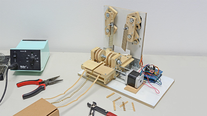
If you have ever assembled a batch of through-hole electronics kits, you know the tiny villain hiding in plain sight: resistor prep. One resistor? Fine. Ten resistors? Still charming. Two hundred resistors on paper tape that need to be separated, counted, trimmed, and organized? Suddenly, you are questioning your life choices while holding a pair of cutters like a medieval tool.
That is exactly where a resistor cutting robot earns its bench space. This small DIY machine feeds taped axial resistors forward, measures the spacing, cuts them into the quantity or length you want, and turns a repetitive hand task into a satisfyingly mechanical process. It is not just a gadget for people who like robots because robots are coolalthough, yes, robots are cool. It is a practical shop assistant for makers, educators, electronics kit sellers, repair technicians, and anyone who regularly handles resistor reels.
In this guide, we will explore how a resistor cutting robot works, what parts you need, how to design the feeding and cutting mechanism, what software logic makes it reliable, and how to avoid the classic DIY-machine problems: slipping tape, crooked cuts, angry servos, and the mysterious screw that always disappears into another dimension.
What Is a Resistor Cutting Robot?
A resistor cutting robot is a small automated machine designed to process resistors supplied on paper tape or bandoliers. Instead of manually counting and cutting components with scissors or flush cutters, the robot advances the taped strip using a motorized feed mechanism, stops at a programmed interval, and activates a cutting system to separate the resistor section.
Most DIY versions use a microcontroller such as an Arduino Nano or Uno, a stepper motor for controlled feeding, and either servos, steppers, or a linkage-driven blade system for cutting. The frame can be made from laser-cut plywood, acrylic, aluminum extrusion, 3D-printed parts, or whatever sturdy material your workshop has not already turned into “future project storage.”
Why Build One Instead of Buying One?
Commercial component lead cutting and forming machines exist, and they can be fast, accurate, and impressive. They are also often more expensive than a hobbyist or small kit maker needs. If you are running a full electronics assembly line, buy professional equipment. If you are preparing resistor packs for classroom kits, small-batch PCB builds, or weekend projects, a DIY resistor cutting robot is a far more approachable solution.
Key Benefits
Speed: Once tuned, the robot can cut dozens or hundreds of resistors with far less hand effort.
Consistency: A fixed feed distance gives you repeatable resistor counts or segment lengths.
Reduced fatigue: Your hands will thank you after the first batch.
Better organization: You can prepare exact quantities for kits, bins, or production runs.
Learning value: The project teaches motion control, mechanical design, motor calibration, cutting force, user interfaces, and safety.
How the Robot Works
The core process is simple: feed, stop, cut, repeat. The challenge is making each step reliable.
1. Feeding the Resistor Tape
Taped resistors are held between two paper strips, usually with predictable spacing between components. The machine uses a roller, wheel, gear, or friction drive to pull the tape forward. A stepper motor is ideal because it moves in known increments. For example, a common stepper motor may rotate in small steps, and with a wheel of known diameter, you can calculate how many steps advance the tape by one resistor pitch.
The feed system should grip the tape firmly without crushing the resistor body or tearing the paper. Rubber O-rings, knurled rollers, or soft drive wheels work well. A spring-loaded idler wheel can help maintain pressure as the tape thickness changes slightly.
2. Positioning the Cut
The robot must stop at the correct place before cutting. In a basic design, you calibrate the number of motor steps needed to move from one cut point to the next. In a more advanced version, optical sensors can detect printed tape holes, component bodies, or contrast marks. For most home builds, step-counting is enough if the feed roller does not slip.
3. Cutting the Tape
The cutting mechanism can be built several ways. A servo can swing a blade downward like a tiny guillotine. A stepper motor can drive a linkage for more controlled force. A solenoid can punch quickly, although it may be louder and harder on the frame. Razor blades, craft blades, or sharpened shear-style cutters can work, but they must be mounted securely and guarded carefully.
A clean cut matters. If the blade drags, twists, or pinches, the tape can jam. The best cutting systems support the tape on both sides of the cut and guide the blade through a narrow slot. Think “paper cutter,” not “angry knife taped to a servo horn.”
Parts You Will Need
Electronics
A practical resistor cutting robot can be built with affordable components:
- Arduino Nano, Uno, or compatible microcontroller
- NEMA 17 stepper motor or smaller stepper for tape feeding
- A4988, DRV8825, TMC2209, or similar stepper driver
- One or two metal-gear servos, or a second stepper motor for the cutter
- 12V power supply for motors
- 5V regulator or buck converter for logic and servos
- Push buttons, rotary encoder, or keypad for input
- OLED or LCD display for quantity and settings
- Emergency stop switch
- Limit switch or homing sensor, optional but useful
Mechanical Parts
- Frame material such as plywood, acrylic, aluminum extrusion, or 3D-printed brackets
- Feed roller with rubber grip
- Spring-loaded idler roller
- Blade holder
- Replaceable razor or cutter blade
- Bearings, shafts, screws, and spacers
- Tape guide channel
- Collection tray for cut resistor strips
- Clear acrylic guard for the blade area
Designing the Feed Mechanism
The feed mechanism is the heart of the machine. If the tape advances accurately, everything else becomes easier. If the tape slips, the robot becomes a random resistor confetti generator.
Start by measuring the resistor tape pitch. Many taped axial components use regular spacing, but you should measure your actual stock with calipers. Mark a line on the tape, advance it manually, and measure how far the strip travels per motor revolution. Then calculate the steps per millimeter.
For example, suppose your feed wheel has a circumference of 40 mm and your stepper has 200 full steps per revolution. Without microstepping, each full step moves the tape 0.2 mm. With 8x microstepping, each microstep is about 0.025 mm in theory. In reality, friction, tape stretch, and wheel compression reduce perfection, so calibration beats math every time.
A good feed path includes three zones: an entry guide, a driven roller area, and an exit guide near the blade. The tape should stay flat and centered. Avoid long unsupported spans because paper tape can curl, buckle, or wander sideways like it has somewhere better to be.
Building the Cutting Head
The cutting head should be rigid, repeatable, and safe. A simple servo-powered blade can work for light paper tape. Use a metal-gear servo because plastic gears may not enjoy repeated cutting loads. Mount the blade at a slight angle so it slices progressively instead of slamming straight down across the entire width.
If you want a more robust design, use a stepper motor with a cam or crank linkage. This gives smoother motion and more torque. A guillotine-style blade sliding in vertical rails is another dependable option. Linear rails are helpful but not required; carefully aligned printed or machined guides can also work.
Whichever method you choose, add a replaceable cutting surface under the tape. A small strip of cutting mat, nylon, or sacrificial plastic can help preserve the blade. Do not cut directly into metal unless you enjoy sharpening things more than building things.
Programming the Robot
The software does not need to be complicated. A basic program should let the user set the number of resistors to cut, the feed distance, and the number of batches. The machine then repeats a predictable sequence:
- Read user input.
- Advance tape by calibrated distance.
- Pause briefly to let the tape settle.
- Activate cutter.
- Return cutter to home position.
- Repeat until the count is complete.
For better reliability, include acceleration and deceleration for the feed motor. Sudden starts can slip the tape, especially with smooth paper. Libraries such as AccelStepper are popular for this reason, though a simple step pulse routine can also work.
Useful Software Features
- Calibration mode: Move the tape forward in small increments until the cut point is correct.
- Manual jog: Feed forward or backward for loading.
- Batch memory: Store common quantities such as 10, 25, 50, and 100.
- Cutter test: Activate the blade without feeding tape.
- Jam timeout: Stop the machine if the cutter does not return or the feed takes too long.
- Emergency stop: Immediately disable motors and cutter movement.
Safety First: Tiny Parts Can Still Bite
A resistor cutting robot may look harmless, but it combines sharp blades, motors, flying clipped material, and exposed electronics. Wear safety glasses while testing and cutting. Component leads and tape fragments can launch unexpectedly, and your eyes deserve better than becoming a parts bin.
Cover the blade area with a clear guard so you can watch the cut without placing fingers near the mechanism. Add an emergency stop button in an easy-to-reach location. Keep loose wires away from moving rollers. If you use a high-current motor driver, set the current limit correctly and provide ventilation for the driver module.
Also remember that servos and steppers can move unexpectedly when code resets or power is applied. During early testing, remove the blade and use cardboard or a dull mock-up cutter. The machine does not need to be dangerous to be educational.
Common Problems and Fixes
The Tape Slips
Increase roller pressure, use a softer drive wheel, slow down acceleration, or clean dust from the roller. If the tape still slips, add a second driven roller or improve the guide path.
The Cuts Are Crooked
Check whether the tape is entering the blade at an angle. Add side guides near the cutting point. Make sure the blade is rigid and not flexing during the cut.
The Servo Stalls
Use a stronger metal-gear servo, sharpen or replace the blade, reduce cutting width, or switch to a cam-driven stepper mechanism. Also confirm the servo has a separate power supply with enough current.
The Count Is Off After Many Cuts
This usually means cumulative feed error. Recalibrate steps per cut, reduce speed, improve roller grip, or add an optical sensor for feedback.
The Blade Tears Instead of Slicing
Use a sharper blade, angle the cut, support the tape better, and replace the sacrificial cutting surface. Paper tape cuts best when it is held flat and cannot buckle.
Practical Upgrades Worth Adding
Once the basic robot works, upgrades can make it feel like a real bench tool instead of a science fair project with ambition.
Optical Detection
An infrared sensor or photointerrupter can detect tape holes, contrast changes, or resistor bodies. This reduces reliance on pure step counting and helps correct small feed errors.
Adjustable Tape Guides
Different component tapes may vary in width. Adjustable guides let the machine handle resistors, diodes, small capacitors, and other axial components.
Quantity Presets
If you often prepare electronics kits, presets save time. A small display with a rotary encoder can make the interface fast and pleasant.
Collection Bins
A sloped chute or removable tray keeps cut resistor strips organized. For kit production, label bins by value before cutting so you do not create a mystery pile of beige cylinders and regret.
Who Should Build This Project?
This project is ideal for intermediate makers. You do not need to be a robotics engineer, but you should be comfortable with basic Arduino wiring, motor drivers, simple mechanical alignment, and safe tool use. If you have built a 3D printer upgrade, CNC accessory, soldering station, or small automation project, you are ready.
Beginners can still build a simplified version. Start with manual feed and servo cutting, then add motorized feeding later. The best DIY machines evolve in stages. The worst ones try to become industrial equipment on day one and end up as expensive drawer decorations.
Real-World Uses
A resistor cutting robot is useful anywhere repetitive component preparation slows down the workflow. Teachers can prepare classroom electronics kits. Makerspaces can organize parts for workshops. Small online sellers can package resistor assortments. Repair shops can create consistent component bundles. Hobbyists can finally stop cutting resistor tape by hand while pretending it is “relaxing.”
The same concept can also be adapted for diodes, taped LEDs, small capacitors, or other bandoliered components. With careful mechanical changes, the robot can become a general axial component preparation tool.
Builder Experience: Lessons From the Bench
The first thing you learn while building a resistor cutting robot is that “simple” mechanisms are rarely simple once real materials are involved. On paper, feeding a strip forward and cutting it sounds like a five-minute problem. On the bench, the tape curls, the roller slips, the blade drags, and the servo makes a noise that sounds suspiciously like it is filing a complaint with management.
One practical lesson is to prototype the feed path before designing the final frame. Tape behavior matters more than the CAD model suggests. A resistor reel may look flat, but once it has been stored for months, it often remembers the curve of the reel. If your entry guide is too short, the strip can wander. If your roller pressure is too high, the paper deforms. If it is too low, the tape slips. The sweet spot usually comes from testing, not guessing.
Another lesson is to separate the machine into modules. Build the feeder as one unit, the cutter as another, and the control panel as a third. Modular design makes troubleshooting easier. When the machine misbehaves, you can test the feeder without the blade, the cutter without the tape, and the software without risking a tiny paper avalanche. It also makes future upgrades less painful.
Blade choice is surprisingly important. A dull blade creates more problems than weak motors. It increases cutting force, bends the tape, stresses the servo, and produces fuzzy edges. A sharp, replaceable blade mounted at a slight angle works much better. Many builders discover that slicing beats chopping. A progressive cut reduces peak force and makes the machine quieter.
Power is another area where small mistakes become big mysteries. Servos should not be powered directly from the Arduino’s 5V pin when they are doing real mechanical work. Use a separate regulated supply with a shared ground. Stepper drivers need current limiting and cooling. If the machine resets every time the cutter moves, the problem is probably not haunted firmware. It is usually voltage sag.
Calibration should be treated as a feature, not a chore. Add a menu option that lets you jog the tape forward by small increments and save the feed distance. Different resistor tapes may require different values. Even two reels from different suppliers can behave slightly differently. A flexible calibration mode turns the robot from a delicate experiment into a usable tool.
Finally, do not underestimate the joy of watching the finished machine work. There is something deeply satisfying about pressing a button and seeing a neat batch of resistors drop into a tray. It is the kind of project that reminds you why DIY automation is fun: not because every task must be automated, but because solving a boring problem with a clever little machine feels like giving your workbench a tiny superpower.
Conclusion
A resistor cutting robot you can build is more than a novelty project. It is a compact lesson in automation, mechanical design, electronics workflow, and practical problem-solving. With a microcontroller, a stepper-driven feed system, a safe cutting head, and patient calibration, you can turn tedious resistor prep into a repeatable process.
The best version is not necessarily the fanciest. It is the one that feeds reliably, cuts cleanly, protects your fingers, and makes your next batch of electronics kits less boring. Build it in stages, test each mechanism carefully, and let the robot do what robots do best: take a repetitive job and perform it without sighing dramatically.